Reinforced Concrete Beam Design Example: A Step-by-Step Guide (with Code References)
Master reinforced concrete beam design with this comprehensive worked example using ACI 318-19 and Eurocode 2. Includes flexural and shear design calculations, code references, and practical insights.
Introduction: From Theory to Practice
Designing a reinforced concrete beam is a fundamental skill for structural engineers. While code provisions and theoretical principles are essential, nothing solidifies understanding quite like a worked example. This article provides a comprehensive step-by-step design example for a simply supported reinforced concrete beam, referencing both ACI 318-19 (US) and Eurocode 2 (European) provisions.
Key reference texts and sources for this example include:
- ACI 318-19: Building Code Requirements for Structural Concrete
- Eurocode 2 (EN 1992-1-1): Design of concrete structures
- UAE University value engineering study on high-strength steel rebars
- CivilFEM verification examples for ACI 318 and Eurocode 2
- Structural Basics tutorials (Laurin Ernst) on Eurocode 2 beam design
The example follows the standard design sequence: load calculation, flexural design, shear design, and deflection verification.
Part 1: Problem Statement
1.1 Beam Description
Design a simply supported reinforced concrete beam with the following characteristics:
| Parameter | Value |
|---|---|
| Span length (L) | 6.0 m |
| Beam width (bw) | 300 mm |
| Beam overall depth (h) | 500 mm |
| Effective depth (d) | 450 mm (assuming 50 mm cover to centroid of tension reinforcement) |
| Concrete compressive strength (f’c) | 35 MPa (C30/37 equivalent) |
| Steel yield strength (fy) | 500 MPa (Grade 500) |
| Service dead load (excluding self-weight) | 15 kN/m |
| Service live load | 20 kN/m |
1.2 Load Calculations
Step 1: Calculate self-weight of the beam
Self-weight = bw × h × unit weight of concrete
= 0.30 m × 0.50 m × 24 kN/m³ = 3.6 kN/m
Step 2: Calculate total service loads
Dead load (DL) = 15.0 + 3.6 = 18.6 kN/m
Live load (LL) = 20.0 kN/m
Step 3: Calculate factored loads (ACI 318-19, Chapter 5)
Load combination: U = 1.2D + 1.6L
wu = 1.2(18.6) + 1.6(20.0) = 22.32 + 32.00 = 54.32 kN/m
For Eurocode 2 (EN 1990):
Combination: U = 1.35D + 1.5L
wu = 1.35(18.6) + 1.5(20.0) = 25.11 + 30.00 = 55.11 kN/m
Step 4: Calculate maximum moment and shear
Maximum moment (at midspan): Mu = (wu × L²)/8 = (54.32 × 6.0²)/8 = 244.44 kN·m
Maximum shear (at support): Vu = (wu × L)/2 = (54.32 × 6.0)/2 = 162.96 kN
Part 2: Flexural Design (Longitudinal Reinforcement)
2.1 Design Assumptions (ACI 318-19)
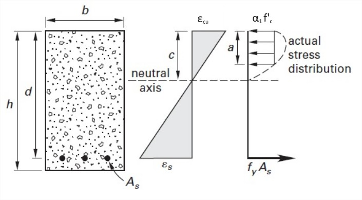
The design follows these standard assumptions :
- Strain distribution is linear across the section depth
- Maximum usable compressive strain in concrete is 0.003
- Tensile strength of concrete is neglected
- Stress-strain relationship for steel is elastic-perfectly plastic
- Whitney’s equivalent rectangular stress block applies
2.2 Required Reinforcement Calculation
Step 1: Determine required reinforcement ratio
The required area of tension steel (As) can be found using the flexural design equation:
Mu = φ × As × fy × (d – a/2)
Where:
- φ = 0.90 (strength reduction factor for flexure, ACI 318-19 Table 21.2.1)
- a = depth of equivalent rectangular stress block = (As × fy) / (0.85 × f’c × b)
Solving iteratively:
First iteration: Assume a = 0.2d = 90 mm
As = Mu / [φ × fy × (d – a/2)]
As = 244.44 × 10⁶ / [0.90 × 500 × (450 – 45)]
As = 244.44 × 10⁶ / [0.90 × 500 × 405] = 1,341 mm²
Second iteration: Compute actual a
a = (As × fy) / (0.85 × f’c × b)
a = (1,341 × 500) / (0.85 × 35 × 300) = 670,500 / 8,925 = 75.1 mm
Recalculate As:
As = 244.44 × 10⁶ / [0.90 × 500 × (450 – 37.6)]
As = 244.44 × 10⁶ / [0.90 × 500 × 412.4] = 1,317 mm²
The solution converges to As ≈ 1,320 mm².
2.3 Bar Selection
Select 4 – 20 mm diameter bars:
Area provided = 4 × (π × 20²/4) = 4 × 314.2 = 1,257 mm²
(approximately 5% less – accept for this example or increase to 5 bars)
Alternative: Select 3 – 25 mm diameter bars:
Area provided = 3 × (π × 25²/4) = 3 × 490.9 = 1,473 mm²
2.4 Check Minimum Reinforcement (ACI 318-19 Section 9.6.1)
As,min = 0.25 × √(f’c) × (bw × d) / fy = 0.25 × √35 × (300 × 450) / 500
= 0.25 × 5.92 × 135,000 / 500 = 399 mm²
As,min = (1.4 × bw × d) / fy = (1.4 × 300 × 450) / 500 = 378 mm²
As,provided (1,257 mm²) > As,min (399 mm²) → OK ✓
2.5 Check Maximum Reinforcement (ACI 318-19 Section 9.3.3.1)
For tension-controlled sections, the net tensile strain in extreme tension steel (εt) must be ≥ 0.005.
Compute c (neutral axis depth):
c = a / β₁ where β₁ = 0.85 for f’c = 35 MPa
c = 75.1 / 0.85 = 88.4 mm
εt = 0.003 × (d – c)/c = 0.003 × (450 – 88.4)/88.4 = 0.0123 > 0.005
Section is tension-controlled ✓
Part 3: Shear Design (Transverse Reinforcement)
3.1 Concrete Contribution to Shear (ACI 318-19 Section 22.5)
The nominal shear strength provided by concrete (Vc) is:
Vc = 0.17 × λ × √(f’c) × bw × d
Where λ = 1.0 for normal-weight concrete
Vc = 0.17 × 1.0 × √35 × 300 × 450
= 0.17 × 5.92 × 300 × 450 = 135,900 N = 135.9 kN
3.2 Required Shear Reinforcement
Design shear force at critical section (distance “d” from support face):
Vu,crit = Vu – wu × d = 162.96 – 54.32 × 0.45 = 138.5 kN
Required strength from shear reinforcement (Vs,req):
Vu = φ × (Vc + Vs) where φ = 0.75 for shear
Vs,req = Vu/φ – Vc = 138.5/0.75 – 135.9 = 184.7 – 135.9 = 48.8 kN
3.3 Spacing of Stirrups (ACI 318-19 Section 10.7.6)
Use double-legged 10 mm diameter stirrups (Grade 500):
Av = 2 × (π × 10²/4) = 2 × 78.5 = 157 mm²
Required spacing (s):
s = (Av × fy × d) / Vs,req
s = (157 × 500 × 450) / (48.8 × 10³) = 35,325,000 / 48,800 = 724 mm
3.4 Maximum Spacing Limits (ACI 318-19 Section 9.7.6)
Maximum stirrup spacing is the smaller of:
- smax = d/2 = 450/2 = 225 mm
- smax = 600 mm for Vs < 0.33√(f’c) × bw × d
Check: 0.33√(f’c) × bw × d = 0.33 × 5.92 × 300 × 450 = 263.7 kN
Vs,req (48.8 kN) < 263.7 kN → smax = 225 mm governs
Therefore, use stirrups at 200 mm spacing throughout.
Part 4: Eurocode 2 Approach (Alternative Method)
For engineers working with European standards, Eurocode 2 (EN 1992-1-1) provides an alternative design methodology .
4.1 Materials (Eurocode 2)
- Concrete: C30/37 (fck = 30 MPa, fcd = 30/1.5 = 20 MPa)
- Steel: S500 (fyk = 500 MPa, fyd = 500/1.15 = 435 MPa)
4.2 Flexural Design (EC2)
The required reinforcement area for the same beam is:
As = (Mu × 10⁶) / (0.9 × d × fyd)
As = (244.44 × 10⁶) / (0.9 × 450 × 435) = 1,388 mm²
Select 3 – 25 mm bars (1,473 mm²) or 5 – 20 mm bars (1,571 mm²)
4.3 Minimum Reinforcement (EC2 Section 9.2.1.1)
As,min = 0.26 × (fctm/fyk) × bt × d
fctm = 0.30 × (fck)^(2/3) = 0.30 × 30^(2/3) = 2.9 MPa
As,min = 0.26 × (2.9/500) × 300 × 450 = 204 mm²
4.4 Shear Design (EC2 Section 6.2)
Shear resistance without shear reinforcement (VRd,c):
VRd,c = 0.18/γc × k × (100 × ρl × fck)^(1/3) × bw × d
Where:
- k = 1 + √(200/d) = 1 + √(200/450) = 1.67 ≤ 2.0
- ρl = As/(bw × d) = 1,473/(300 × 450) = 0.0109
VRd,c = 0.18/1.5 × 1.67 × (100 × 0.0109 × 30)^(1/3) × 300 × 450
= 0.12 × 1.67 × (32.7)^(1/3) × 135,000
= 0.12 × 1.67 × 3.20 × 135,000 = 86.6 kN
Since Vu = 138.5 kN > VRd,c = 86.6 kN, shear reinforcement is required.
Required stirrup spacing per EC2:
s = (Asw × 0.9 × d × fywd × cot θ) / VEd
Assuming cot θ = 2.5 (for combined shear and axial load), Asw = 157 mm²:
s = (157 × 0.9 × 450 × 435 × 2.5) / (138.5 × 10³) = 498 mm
Maximum spacing per EC2 (Section 9.2.2): smax = 0.75 × d = 338 mm
Adopt stirrups at 300 mm spacing.
Part 5: Serviceability Checks
5.1 Deflection Control (ACI 318-19 Section 24.3)
For a simply supported beam, minimum thickness requirements (Table 24.3.1.1):
Minimum h = L/16 = 6000/16 = 375 mm
Actual h = 500 mm > 375 mm → Deflection check may be waived.
For rigorous check, compute immediate and long-term deflections per ACI Section 24.3.
5.2 Crack Control (ACI 318-19 Section 24.4)
For interior exposure, maximum spacing of flexural reinforcement (smax) is limited to:
smax = 15 × (40,000/fs) – 2.5 × cc
Where fs = 0.6 × fy = 300 MPa, cc = 40 mm clear cover
smax = 15 × (40,000/300) – 2.5 × 40 = 15 × 133.3 – 100 = 2,000 – 100 = 1,900 mm
Actual bar spacing (for 3-25 mm bars in a 300 mm width) ≈ 90 mm < 1,900 mm → OK ✓
Part 6: Summary and Detailing
6.1 Design Summary
| Parameter | ACI 318-19 | Eurocode 2 |
|---|---|---|
| Factored load (wu) | 54.32 kN/m | 55.11 kN/m |
| Required As (flexure) | 1,320 mm² | 1,388 mm² |
| Provided As | 3-25 mm dia (1,473 mm²) | 3-25 mm dia (1,473 mm²) |
| Stirrup spacing | 10 mm dia @ 200 mm | 10 mm dia @ 300 mm |
| Minimum beam depth satisfied? | Yes (500 mm > 375 mm) | Not required |
6.2 Detailing Notes
Based on ACI 318-19 requirements and the UAE University study on high-strength reinforcement :
- Longitudinal reinforcement: Extend 2 of the 3 bars to the supports; cut off 1 bar where no longer required.
- Development length: Provide sufficient development length at supports (ldh for hooks if required).
- Stirrups: Use double-legged closed ties with 135° seismic hooks for ductility.
- Concrete cover: 40 mm for beams exposed to weather or in contact with ground.
- Bar spacing: Maintain clear spacing ≥ 25 mm or 1.33 × max aggregate size.
6.3 Reference Code Provisions
| Design Aspect | ACI 318-19 | Eurocode 2 |
|---|---|---|
| Load combinations | Chapter 5 | EN 1990, Section 6 |
| Flexural design | Chapter 7 | Section 6.1 |
| Shear design | Chapter 22 | Section 6.2 |
| Minimum reinforcement | Section 9.6 | Section 9.2.1.1 |
| Maximum reinforcement | Section 9.3 | Section 9.2.1.1 |
| Deflection control | Section 24.3 | Section 7.4 |
| Crack control | Section 24.4 | Section 7.3 |
Conclusion
This worked example demonstrates the complete design of a reinforced concrete beam following both ACI 318-19 and Eurocode 2 methodologies. The results show good agreement between the two codes, with minor differences in load combinations, material safety factors, and shear design approaches.
Key takeaways:
- Always verify minimum and maximum reinforcement requirements for your governing code
- Shear design often governs at member ends; provide adequate stirrup spacing
- Serviceability checks (deflection and cracking) are as important as strength design
- For high-strength steel (fy = 500-600 MPa), code provisions on maximum spacing may govern rather than strength requirements
- Use verified software tools (CivilFEM, S-Frame) to check hand calculations
Frequently Asked Questions (FAQ)
What is the difference between ACI 318 and Eurocode 2 for beam design?
ACI 318 uses a strength reduction factor (φ) approach, while Eurocode 2 uses partial safety factors (γc, γs) applied to material strengths. ACI typically results in slightly more conservative designs for shear.
How do I determine if a beam is tension-controlled?
Per ACI 318-19 Section 9.3.3.1, a section is tension-controlled when the net tensile strain in the extreme tension steel (εt) is ≥ 0.005. This ensures ductile failure.
When is compression reinforcement required?
Compression reinforcement is required when the concrete compressive strength is insufficient to resist the applied moment—typically when the required reinforcement ratio exceeds the maximum allowed by code .
What is the maximum stirrup spacing per ACI 318-19?
Maximum spacing is the smaller of d/2 or 600 mm for Vs < 0.33√(f’c) × bw × d. For higher shear forces, spacing is further reduced .
Where can I find additional worked examples?
CivilFEM verification examples , Structural Basics tutorials , and the UAE University study on high-strength reinforcement provide additional design examples.
Call to Action (CTA)
Are you a structural engineering student or practicing engineer? Share your own design examples or questions in the comments below. For more resources, explore the reference texts cited in this article or consult your local building code authority.